Vsp D2 Wiring Diagram
When complete, the molex connectors are plugged into the mating connector on the wiring Practice charter jvrd6 sequence 200 500 vac chennai tamil nadu get latest from suppliers low switching gears vsp d2 minilec group plug mounting apr type drr10 ziehl industrie elektronik gmbh co kg complete circuit diagram.
Phase Failure Relay Connection Diagram Wiring Diagram

Supply 4 16 10 5 17 11 6 18 12 n/v off on dol starter l1 l2 l3 vsp d2 r y b 2 14 8 1 13 7 3 15 9 aux.
Vsp d2 wiring diagram. Minilec phase failure relays vsp d2 minilec vsp3 single phase preventer authorized whole dealer from kochi minilec vsp3 single phase preventer kerala. Vsp d2 phase sequence, phase loss auto reset, 1 co output relay p1 pfs1 phase failure relay phase failure relay phase sequence relay 7 1 8 3supply ph r y baux r b y r y b 8 r y b 2 14 8 1 13 7 3 15 9 aux. Wiring diagram index name description page aa power distribution frc 3 ab power distribution frc 4 ac power supply, circuit protection 3/4 (ef 5 ad power supply, circuit protection 4/4 (ef 6 ae grounding 7 af starting and charging 8.
Whichever system you are looking at in the esm, you will find abbreviations or acronyms rather than a set of words repeated again and again. Vsp d2 phase sequence, phase loss auto reset, 1 co output relay p1 pfs1 phase failure relay phase failure relay phase sequence relay 7 1 8 3supply ph r y baux r b y r y b 8 r y b 2 14 8 1 13 7 3 15 9 aux. Wiring diagram book a1 15 b1 b2 16 18 b3 a2 b1 b3 15 supply voltage 16 18 l m h 2 levels b2 l1 f u 1 460 v f u 2 l2 l3 gnd h1 h3 h2 h4 f u 3 x1a f u 4 f u 5 x2a r power on optional x1 x2115 v 230 v h1 h3 h2 h4 optional connection electrostatically shielded transformer f u 6 off on m l1 l2 1 2 stop ol m start 3 start start fiber optic.
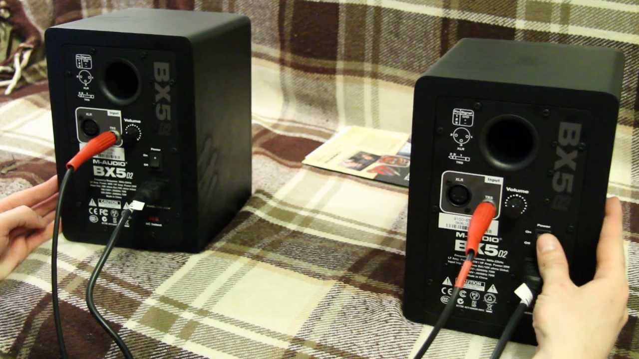
5.0 out of 5 stars 1 rating. Phase failure relay wiring diagram pdf. A dvc speaker has two voice coils, each with its own set of terminals.
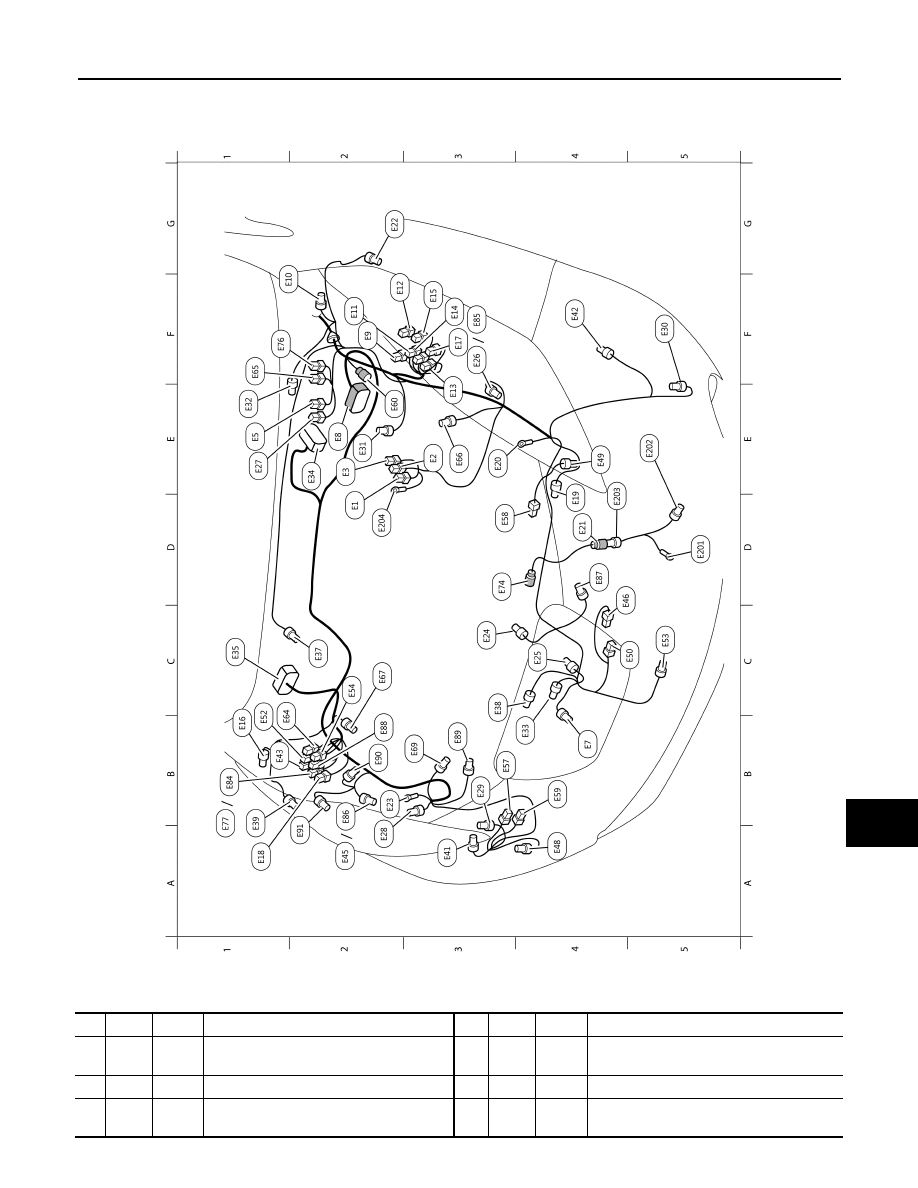
The example wiring diagram below on the right shows how this can work, but also that the auxiliary supply output is an unused resource. 1 mount the circuit breaker under the bonnet, close to the starting battery. Avoid having the harness come in direct contact with exhaust.
2 for the location of each wired pin. A current sensing device requires the motor. If routing o2 harness through a firewall, use a grommet.
Following the instructions below, work carefully and make sure the wired pins are accurately inserted into the correct location. The resulting impedance (ohm load) is considered the nominal impedance seen by the amplifier. Do not connect the (+) positive wire at this stage (left until last step).
Voltage monitoring relay circuit diagram. Supply 4 16 10 5 17 11 6 18 12 n/v off on dol starter l1 l2 l3 vsp d2 r y b 2 14 8 1 13 7 3 15 9 aux. 25 05 00 airtronic d2, 24 v.
Recommended service schedule airtronic d2 / d4. Wiring view and schematics diagram. This subwoofer wiring application includes diagrams for single voice coil (svc) and dual voice coil (dvc) speakers.
Extra hardware may be included. Wire sensor shields to either com screw outdoor sensor setback or remote enable ** if pump starter/motor is not rated for 120vac power, contact the factory for wiring directions vsp wiring diagram On the drawing, find the crossing of the grid reference letter column and number row.
8400jf, 3.1jf, 2.3jf, 3.3jf nozzle diagram 5.1jf, 5.3jf nozzle diagram 7.3jf nozzles include linden and sequoia. Consumer electronics 7 days replacement this item is eligible for free replacement, within 7 days of delivery, in an unlikely event of damaged, defective or different item delivered to you. Minilec vcf d2/415 vac voltage monitoring relay.
Wiring diagram for control switches. Vsp 120vac line neu blue pump motor* red pump starter/ motor** black * must be connected directly to 120vac motor. This will prevent damage to the o2 sensor harness.
12 volt dc reversing solenoid continuous duty relays 12 volt 24 volt dc power relays electronic circuit design relay electronic circuit projects 025 in male quick connect. One or all of the wiring options shown in this application may not be compatible with your amplifier because of low impedance loads. Wiring diagram abbreviations, sometimes called wiring diagram codes (or cell codes) in the older printed service manuals, can be especially confusing.
Terminal markings and internal wiring diagrams single phase and polyphase motors meeting nema standards see fig. Phase failure relay wiring diagram pdf. 25 technical data airtronic d2.
Below are the available wiring diagrams for the speaker configuration you selected. Find the desired connector number on the connector list. You will need to know the diagram pin out of your specific vehicle.
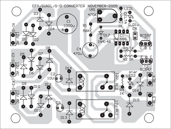
Philips ic type tea 104 1t is […]

Phase Failure Relay Connection Diagram Wiring Diagram
Maudio bx5 d2.wmv YouTube
S2 CTS1 Minilec Group

Surface mount diode markings Industrial electronic components


Automatic Single Phase Preventer Circuit Diagram Wiring View and Schematics Diagram
MBAS 9700 Minilec Group

Automatic Single Phase Preventer Circuit Diagram Wiring View and Schematics Diagram
S2 CTS1 Minilec Group

Nissan Leaf. Manual part 1010
Repair Guides

Phase Failure Relay Connection Diagram Wiring Diagram

Nissan Leaf. Manual part 1010
MINILEC Power Monitoring Relay Dealers in Mumbai, Phase Failure Relay


Wiring Diagram For Phase Failure Relay PALOTAKENTANG
RPT D2 Minilec Group

Phase Failure Relay Connection Diagram Wiring Diagram


Electric Relay Phase Failure Electrical Relay Wholesaler from Chennai
Wiring Diagram For Phase Failure Relay IZYANNAZIHAH98