Water Meter Wiring Diagram
Terminals in the flow meter. A wiring diagram is a simple visual representation of the physical connections and physical layout of your electrical system or circuit.

Neptune Water Meter Wiring Diagram Free Wiring Diagram
Diagramweb.net autometer pyrometer wiring diagram as well as temperature gauge img source.

Water meter wiring diagram. The omni™+ t² meter operation is based on advanced floating ball technology. Aug 15, · autometer pyrometer wiring diagram auto meter ficial site trade in any aftermarket gauges for credit on new autometer gauges 15 trade in trade up read more auto autometer pyrometer wiring diagram isspro electric water temp img source: For sensus and invensys water meters provides wiring information for.
I'd like that data for my home monitoring system. Open the meter outlet valve slowly. 10 awg copper or 8 aluminum wire suggested.
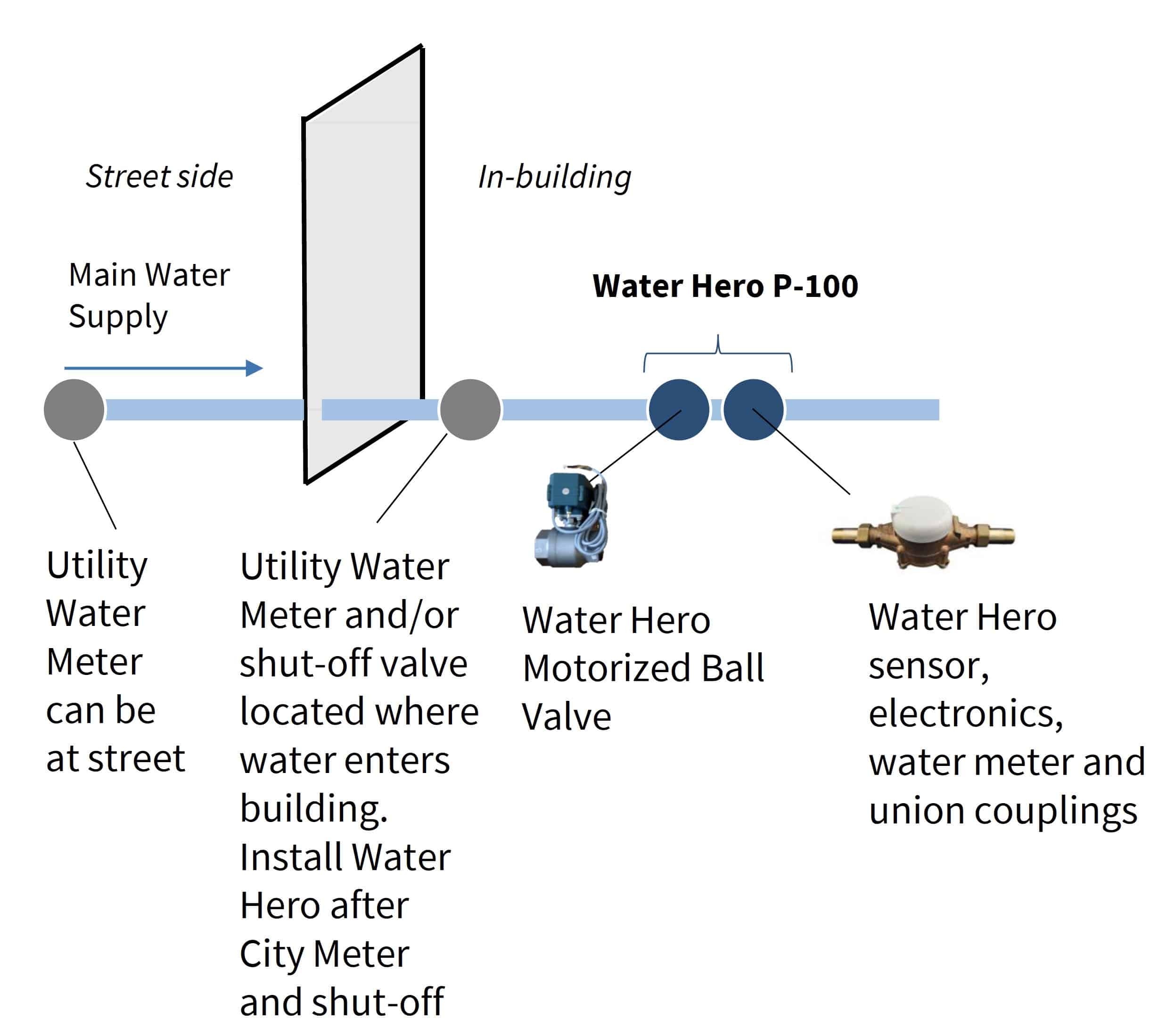
Common ground wire (port 14). Isolation valve (attached to waterline from street) 2. 11/28/2017 campus facilities university of missouri rev
Here is a manual on the water heaters page 25 shows the wiring diagram on the new water heater. • ami infrastructure install new meter; Environmental protection design, food grade pom, pbt material, compact and practical, adjustable at any angle;
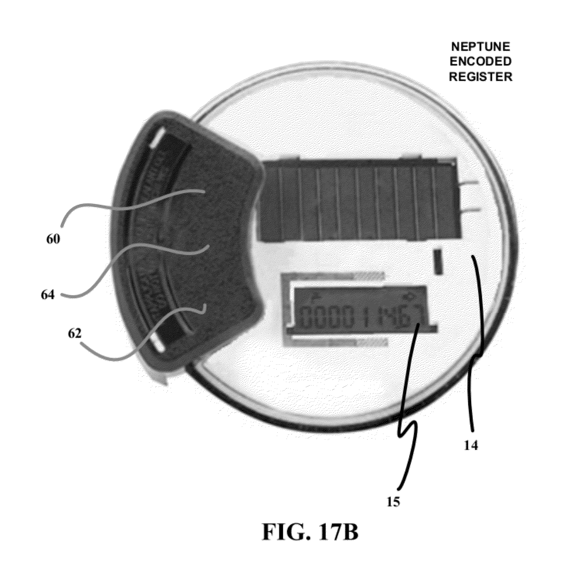
Omni+ turbo (t²) water meter. Interfacing to my neptune water meter. Skip to the flow meter configuration section of this manual (see page 19).
Diagram 3 (page 9) shows, a meter carrier for a single and/or multiple internal meter installation (which. Water meter frost plate (sacrificial black steel, under meter, will break if frozen) 3. If you have questions about the electric vehicle (ev), residential solar, or ground source heat pump wiring diagram, please contact one of our meter technicians at 763.441.2020.
Refer to figure and table for the wiring diagram. Service type project size meter type. These wires can be up to 200 feet long.
Water meter register head 5. An electric water heater s wiring diagram enables someone to completely rewire a water heater even after removing all of the wires and parts. A wiring diagram decal is located adjacent to the field wiring terminals within the fusion enclosure.
Mount mxu to sensus ecr (all variants). On milbank 200 amp meter socket wiring diagram. Form a digital output is high resolution, and can be easily field retrofitted.
Parts with just a click. Introduction of water flow sensor wiring diagram. Water meter wiring diagram date drawing not to scale 12/08/17 date:
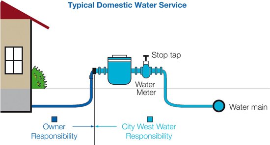
While the faucet is open, verify the meter is operating correctly. Learn the steps for a flawless installation from start to finish. Getting to know your meter assembly diagram of typical meter installation.
120v feed shall be 15a dedicated circuit from panel. The double end is 6mm intubation type structure, which is more convenient to connect and can meet the installation of guests from all angles; The electric main supply 230v ac 120v ac in us is connected through secondary of the transformer 3 phase 4 wire system single phase energy meter and mcbs dp sp to sub circuits and final sub circuits to protect all the connected electrical devices and appliances through electrical wiring installation.
View and download the wiring diagrams for meter installations. If the flow meter is only to be utilized as a flow rate indicator or totalizer, no further wiring will be required. Connect a hot leg into port 7 and the neutral into.
Connect the black wire to port 14 (see fig. Wiring a breaker box diagram strand electric on twitter. Click here to view and print the full size diagram.
The ermu wiring diagram can be a useful tool when working on meter installation. Open a down stream faucet and run enough water to dissipate entrained air and flush the line. Connect the red or white wire from the water meter to either port 11, 12, or 13.
The patented measurement principles of the omni+ t² meter ensure greater accuracy, expanded accuracy range and longer service life than any other comparable class. Dual check backflow preventer (duc) 6. Turn off the faucet and check the meter installation for leaks.
Wiring diagrams for residential water heaters 315267 000. Leave 12 inches extra wiring at each end for owner termination. The tricon® transmitter provides an electronic interface to neptune water meters electrical pulses at a rate corresponding to the rate of flow through the meter.
Sensus Water Meter Wiring Diagram

Neptune Water Meter Wiring Diagram Wiring Schema
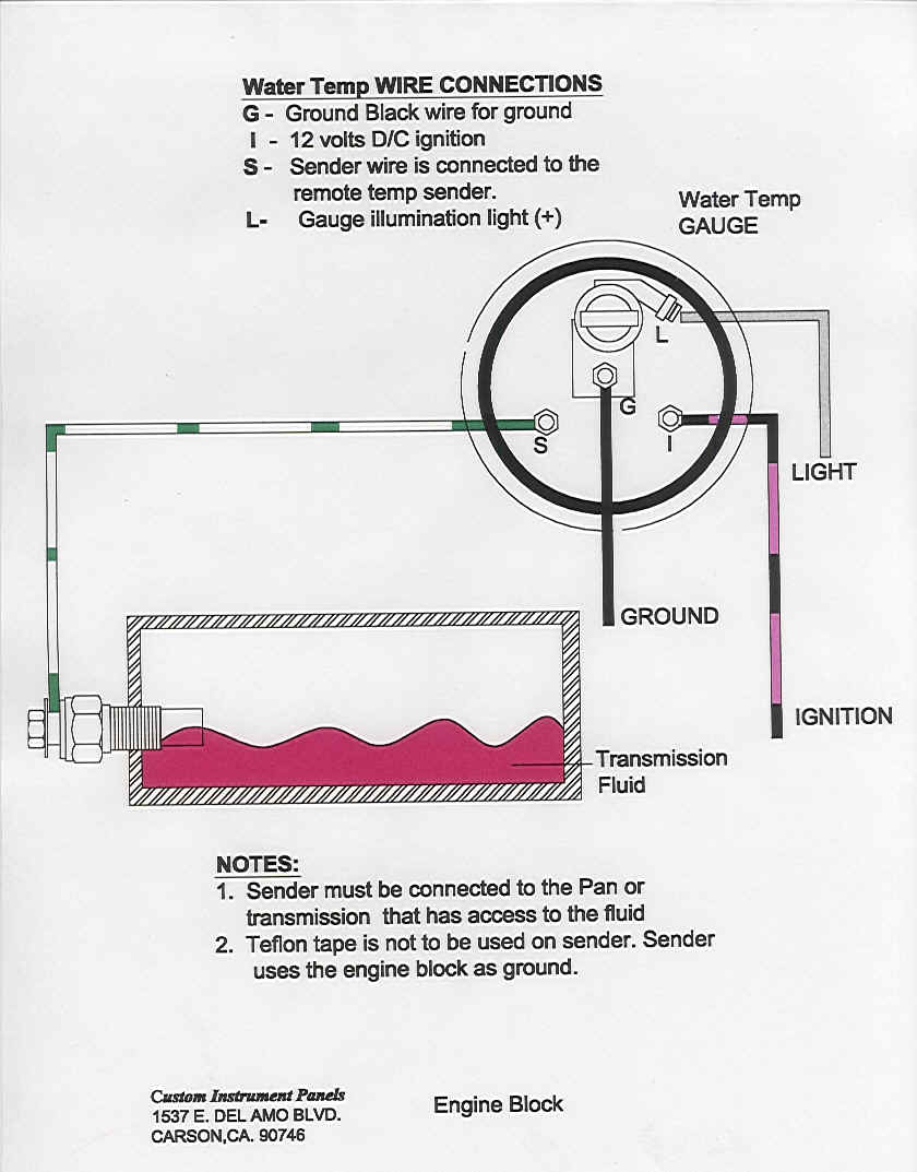
Autometer Water Temp Gauge Wiring

Sensus Water Meter Wiring Diagram

33 Water Meter Installation Diagram Wiring Diagram Database

Autometer Water Temp Gauge Wiring
![]()
Water Corporation Water Meter Locations Meter Access Requirements

Sensus Water Meter Wiring Diagram

Smart Water Meter To Help Control Water Wastage Full DIY Project
Sensus Water Meter Wiring Diagram
Autometer Water Temp Gauge Wiring
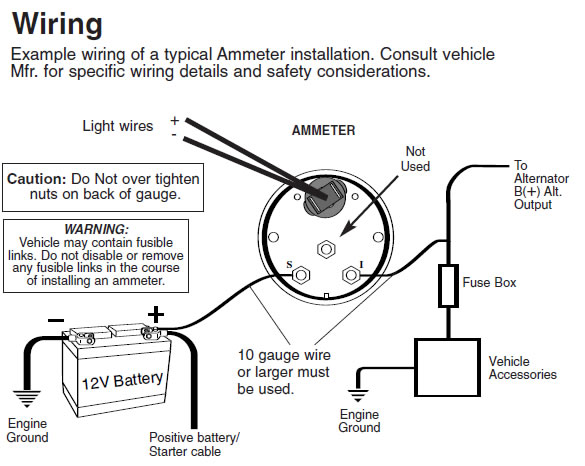
Autometer Water Temp Gauge Wiring

 v2.jpg)
Water Meter Reader Hackster.io

29 Water Meter Installation Diagram Wiring Diagram Ideas
Meter Installation Heritage Springs Water Works, Inc.

33 Water Meter Installation Diagram Wiring Diagram Database
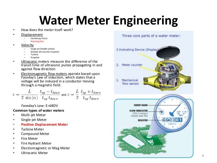
how does a water meter work diagram CCE l ONLINE NEWS
![]()
Neptune Water Meter Wiring Diagram Free Wiring Diagram
29 Water Meter Installation Diagram Wiring Diagram Ideas
